| Tikalon Blog is now in archive mode.
An easily printed and saved version of this article, and a link
to a directory of all articles, can be found below: |
|
This article |
| Directory of all articles |
Control Freaks
October 19, 2010
Many
electrical engineers are control freaks. This applies to their lifestyle as well as to that part of their profession that involves designing
controllers for various processes. I'm guilty on both counts, first because I've designed and built several devices that automatically control the lights in my house;[1] and second, because I've done the same for quite a few electronic control systems for scientific instruments. One of my first major control systems was an interface for an electronic
balance.
During my post-doctoral days at the
University of Pittsburgh, I was privileged to work with Raymond Craig, a talented
physical chemist who made many custom laboratory instruments. Ray had a machine shop in his house, and he would design and create wonderful instruments of finely polished
brass. Many of these were electronic balances that we used in
magnetic measurements. Today, electronic balances are reasonably inexpensive, but they were beyond our research budget in those days. The
operating principle for a
magnetically actuated balance is quite simple. It's just the electronics that are somewhat difficult. Ray had used
vacuum tube circuits for his successful line of balances, and when I saw these in the mid-1970s, I realized it was time for an upgrade.
My controller of choice was a
PID controller, which was easy to implement using
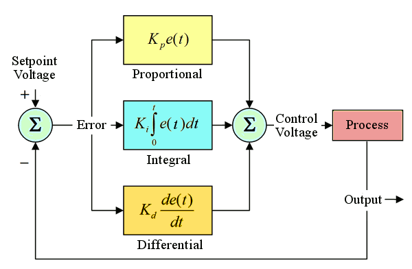
operational amplifiers. PID controllers are named for their principal elements, which derive a control signal that's proportionally related to the deviation from a setpoint (P), its
integral over time (I) and its time
differential (D, see figure). Since our loads were limited to a few tens of grams, supplying current to the magnetic actuator wasn't a problem. The deviation signal, or error signal, in this application is the magnitude of the deviation of the balance beam from its equilibrium position. We used a shutter between two pairs of
LEDs and
photodiodes to get a signal that was proportional to the deviation from this setpoint. These elements were arranged such that movement of the balance beam upwards would generate a negative voltage in a
bridge circuit, and movement of the balance beam downwards would generate a positive voltage. This was the most difficult part of the system, since PID controllers need a relatively linear error signal. Otherwise, they'll
oscillate. Fine crafting of the shutter shape was needed, although a
graduated density optical filter would be preferred.

Functional diagram of a PID Control Loop. The error signal is e(t).
Operational amplifiers make excellent
differential amplifiers,
linear amplifiers for the proportional signal,
integrators and
differentiators, so a PID controller using operational amplifiers is easy to do, and various implementations are available on the Internet.[2] You would not want to make the same type of circuit using vacuum tube operational amplifiers, principally because you would be using a lot of vacuum tubes. The popular vacuum tube operational amplifier, the
Philbrick K2-W, used two 12AX7 tubes, which translates to four
triode amplifiers. There's a further problem of
drift and
dynamic range, although satisfactory performance could be realized by a more complex
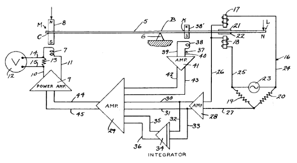
chopper-stabilized operational amplifier. Instead, designers used a systems approach to minimize the required number of vacuum tubes. One example of this is the electronic balance of US Patent No. 2,940,747, shown in the figure. The time derivative signal is generated by a magnet (38') moving in a coil (38). As can be seen at the right hand side of the figure, the error signal is generated by two
inductance coils in a bridge circuit.

Figure 1 from US Patent No. 2,940,747, Harvey P. Elder, et al., "Electric Weighing And Balancing System," June, 1960.
A PID controller is essentially just an equation that converts an error signal into a control signal. Won't a
microcontroller allow construction of a PID controller with fewer parts? Many microcontrollers have internal analog to digital converters, usually 10-bit. In a temperature controller, this translates to one degree out of a thousand degrees, which is likely all the resolution you'll need in most applications. On the output end, many furnaces use what's called
bang-bang control, an expression probably derived from the clanking relays in older controllers. This is just a simple on-off type of control with variable
duty cycle. You just turn on the heating elements when things are looking a little cold, and turn them off when things are getting too hot. The large
thermal mass of the furnace averages things out so that there are no major jumps in temperature. A single output bit on a microcontroller can handle that. For the electronic balance application, the ten bit error signal would be fine, but not the bang-bang output, or any simple pulse-width modulation output. You would need a
digital to analog converter (DAC), but ten bits won't do. If you want to measure a milligram out of ten grams, that's one part in 10,000, or roughly 13-14 bits.
Although all this is easy for an electrical engineer to implement, I didn't mention how you determine the constants you need in the PID equation. Although these can be analytically derived from the
transfer function of the process (e.g., how the furnace reacts to changes in heater voltage), you're just pushing the problem onto another problem; namely, doing that measurement. My PID circuit board contained trim pots to select these values, and I must confess that it was a trial-and-error adjustment based on some
guestimated target values. Nowadays, I would do a
design of experiments approach, using settling time to a certain percentage of the equilibrium value after a step change in error signal as a measure of tuning quality.
As those involved in
biomimetic materials know, Nature has figured out how to do many things well; so well, in fact, that we're trying to duplicate things like
spider silk,
nacre and
beetle husks. Electrical engineering pundit,
Bob Pease,[3] known for his work on vacuum tube operational amplifiers and many other things, pointed out in one of his articles how Nature has mastered control systems.[4] While stopping at a railroad crossing, he noticed that he could turn his head from side to side to check for oncoming trains in about a fifth of a second. He conjectured that his head settled to within 2-4 degrees, enough for his eyes to do the fine tuning required to image the tracks. In that same article, Pease described how
Edison solved his control problem of having each film frame in movie cameras and projectors stop precisely where it should to avoid jitter. He clamped it.[5] No PID loops required.
References:
- D.M. Gualtieri, "Interfacing with the BSR X-10 Home Control System," Microsystems, vol. 4, no. 1 (1983), pp. 88-93. Devlin Gualtieri, "Build an X10 Controller (Part 1)-Circuit Design," Circuit Cellar, Issue #240 (July 2010), pp. 28-34. Devlin Gualtieri, "Build an X10 Controller (Part 2)-The Controller Program and Utility," Circuit Cellar, Issue #241 (August 2010), pp. 36-41.
- Operational Amplifier PID Controllers via Google Search.
- All analog designers know Bob's work and read his magazine column. Every organization needs someone like Bob to keep things real.
- Bob Pease, "What's All This Limerick Stuff, Anyhow?," Electronic Design, October 5, 2010.
- Thomas A. Edison, "Stop Device," US Patent No. 491,993 (February 21, 1893).
Permanent Link to this article
Linked Keywords: Electrical engineers; controllers; balance; University of Pittsburgh; physical chemist; brass; magnetic measurements; electromechanical solenoids">operating principle; magnetically actuators; vacuum tube; PID controller; operational amplifiers; integral; differential; LED; photodiode; bridge circuit; oscillate; graduated density optical filter; differential amplifier; linear amplifier; integrator; differentiator; Philbrick K2-W; triode; bias drift; dynamic range; chopper-stabilized; inductance coils; US Patent No. 2,940,747; microcontroller; bang-bang control; duty cycle; thermal mass; digital to analog converter; transfer function; guestimated; design of experiments; biomimetic materials; spider silk; nacre; beetle husks; Bob Pease; Edison; X10; Microsystems; Circuit Cellar; US Patent No. 491,993.